Figure 1—GS planet carrier TRB.

Figure 2—TRB rollers with micropitting toward large ends.

Figure 3—section of the IR with micropitting and macropitting

Figure 4—section of the IR with severe macropitting.

Figure 5—LOM image of the IR thrust rib.

Figure 6—LOM image of the roller large end with a multitude of scratches.

Figure 7—LOM image of an enlarged view of Figure 6.
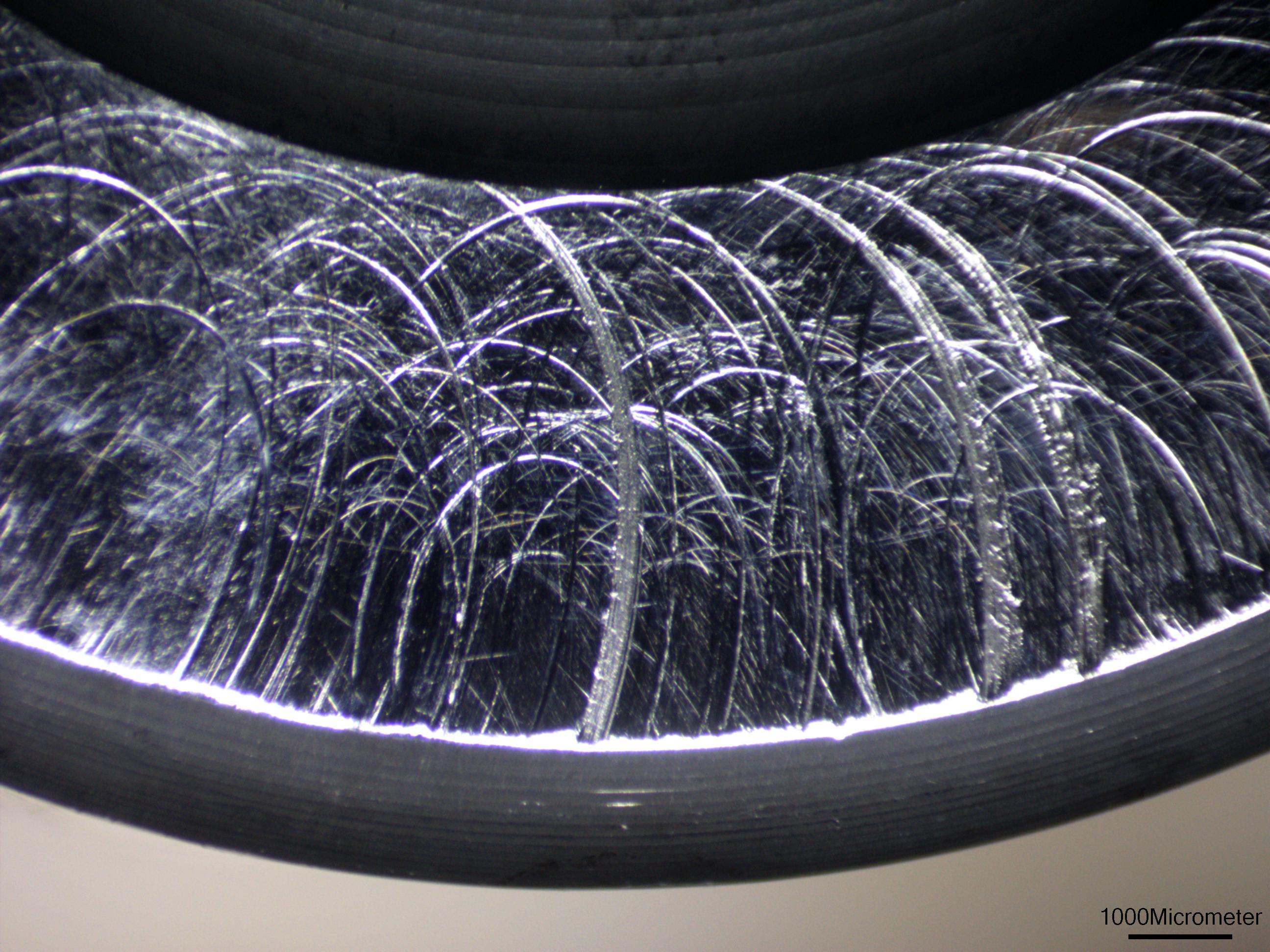
Figure 8—same as Figure 7 except with a different light direction.
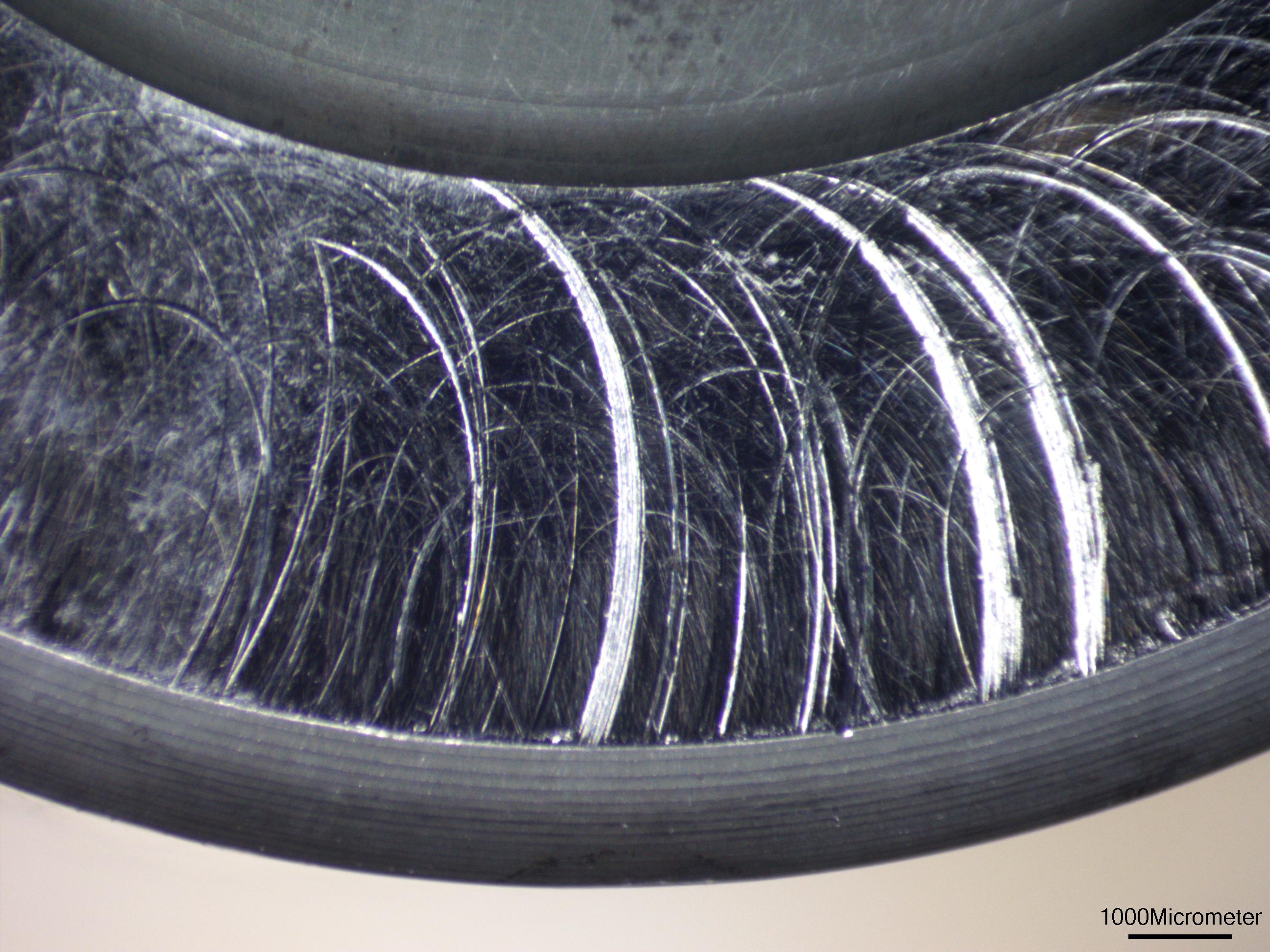
Figure 9—Micropitting biased toward the large end of the OR raceway.
Figure 10—LOM image of the bearing IR raceway at 10x magnification.
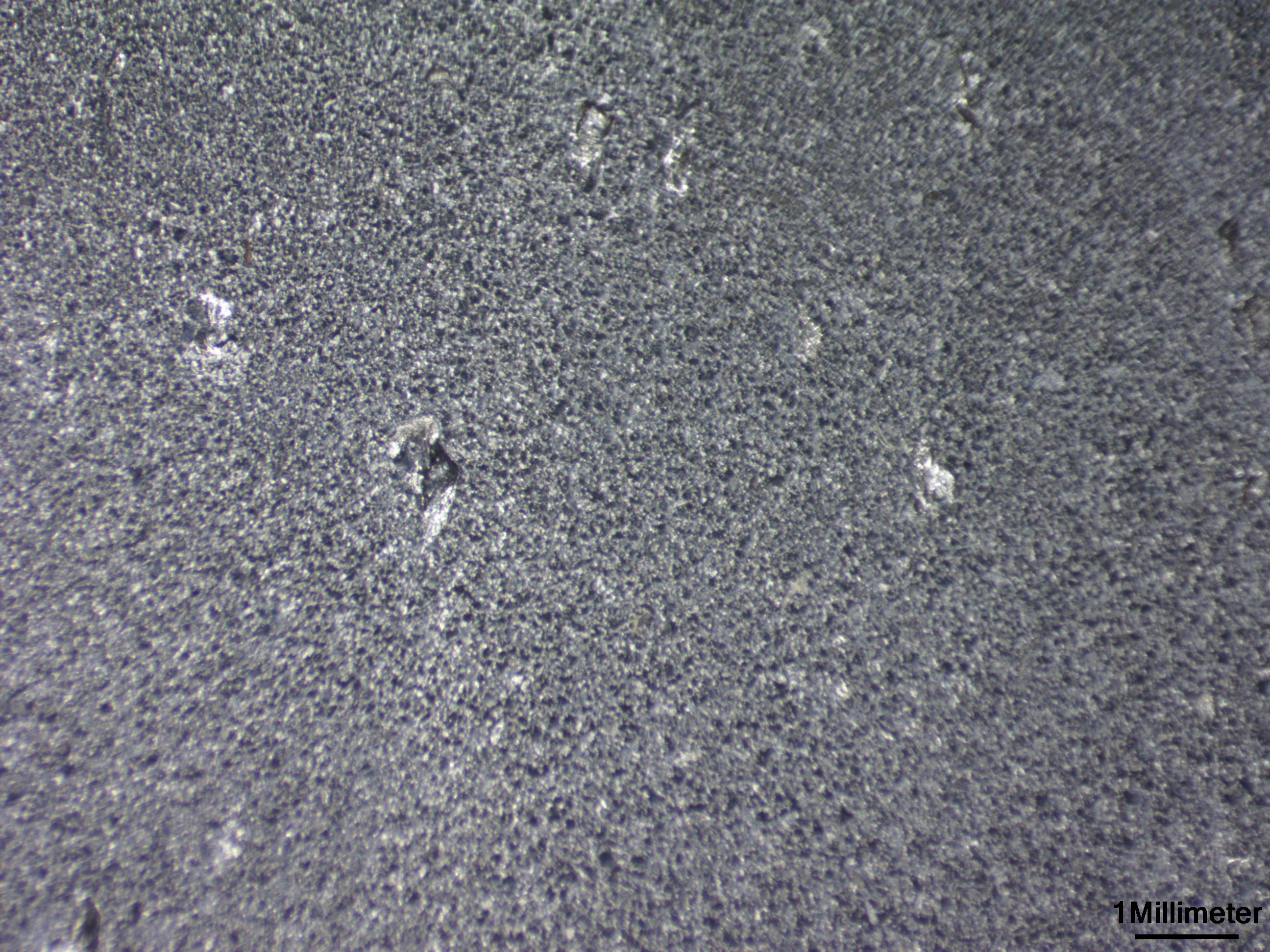
Figure 11—SEM image of the IR raceway at 40x magnification.
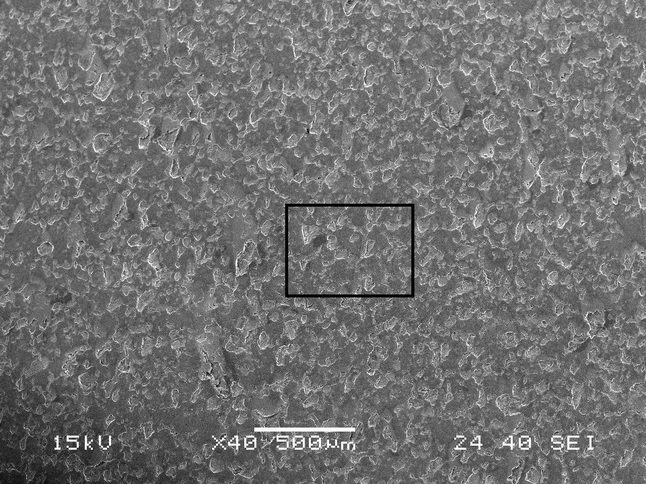
Figure 12—SEM image of the IR raceway at 200x magnification.
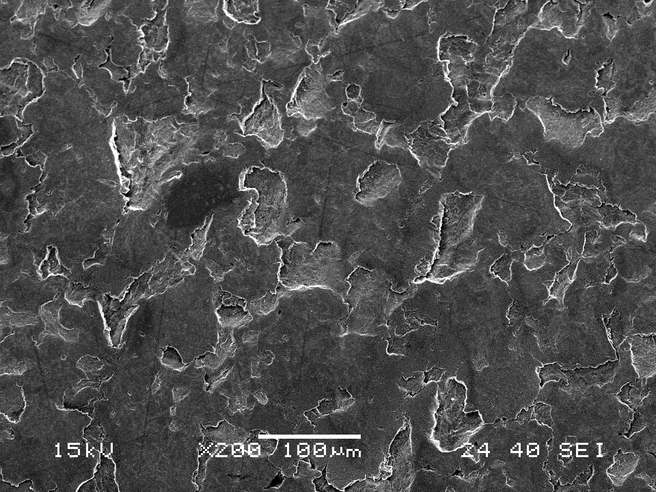
Figure 13—SEM image of macropitting at the edge of the small end of the IR raceway.
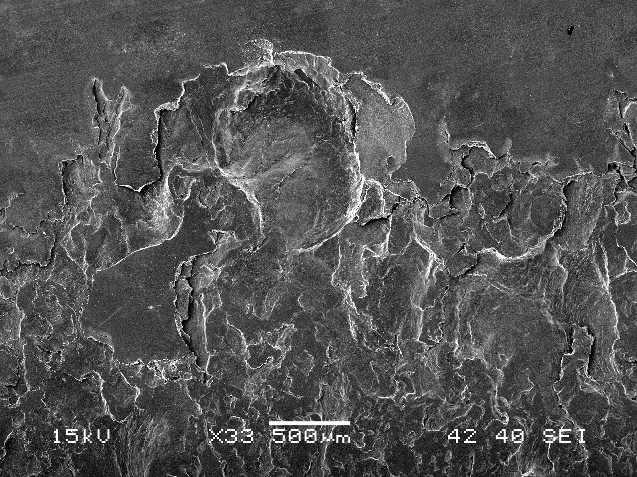
Fig 14—LOM image of roller end (same as Figure 8).
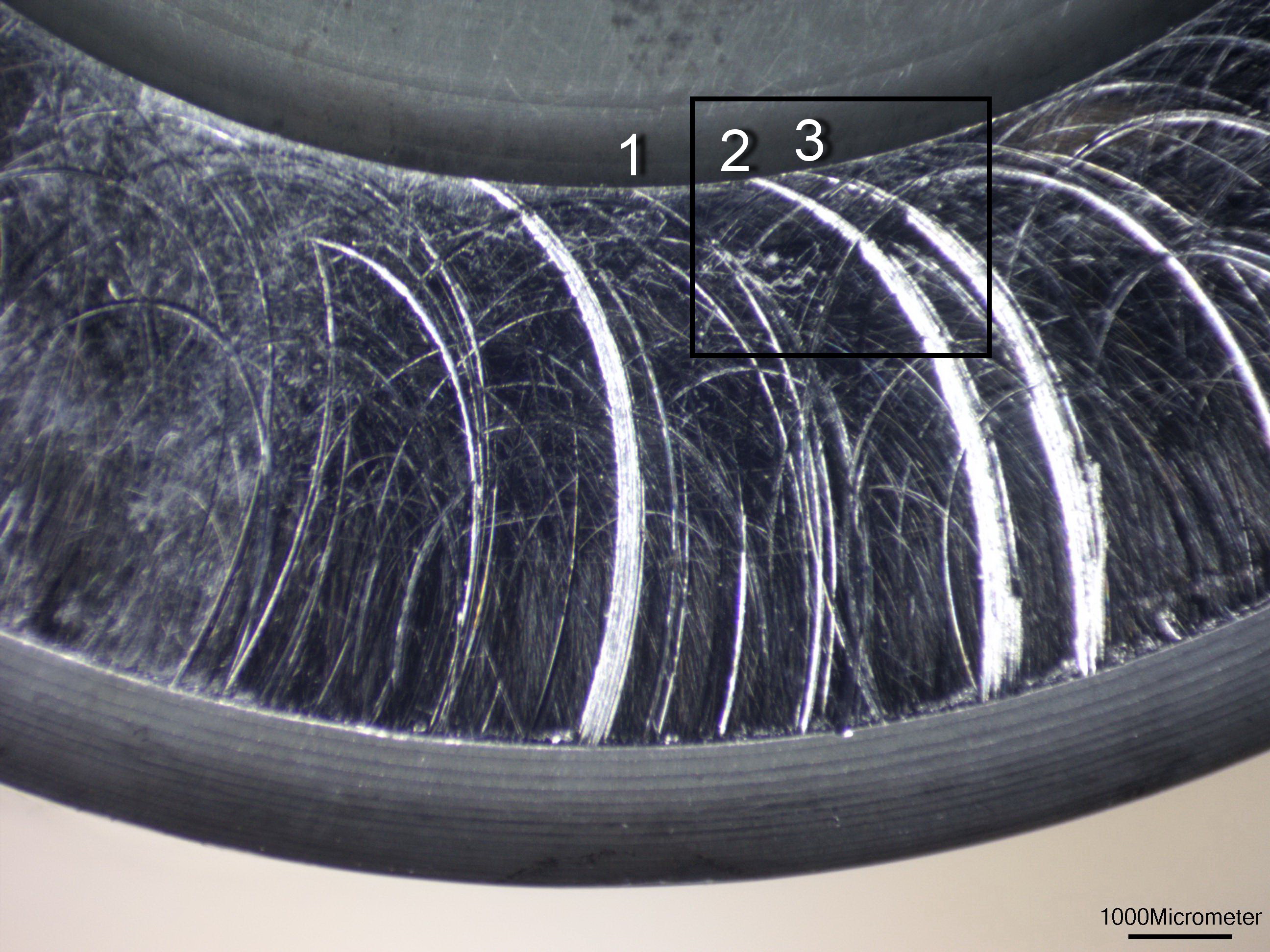
Figure 15—SEM image of the roller end at higher magnification.
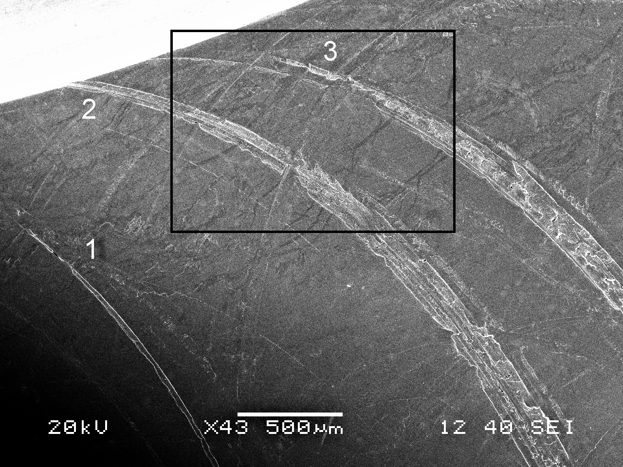
Figure 16—BSE image of Figure 15.
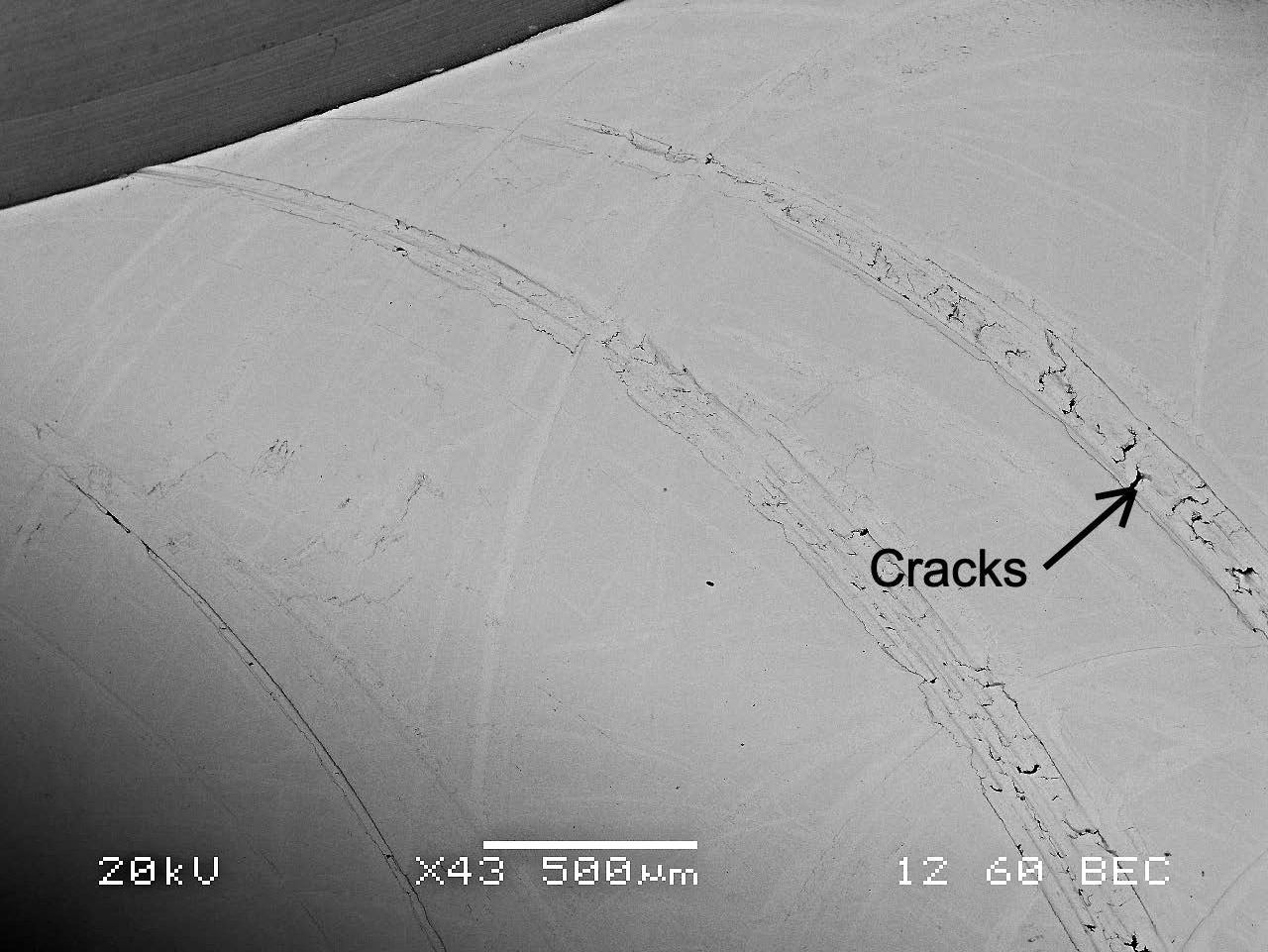
Figure 17—SEM image of roller end at higher magnification.
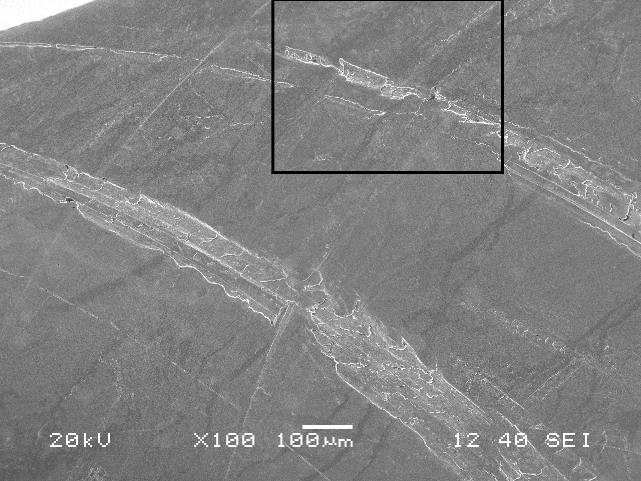
Figure 18—SEM image of roller end at higher magnification.
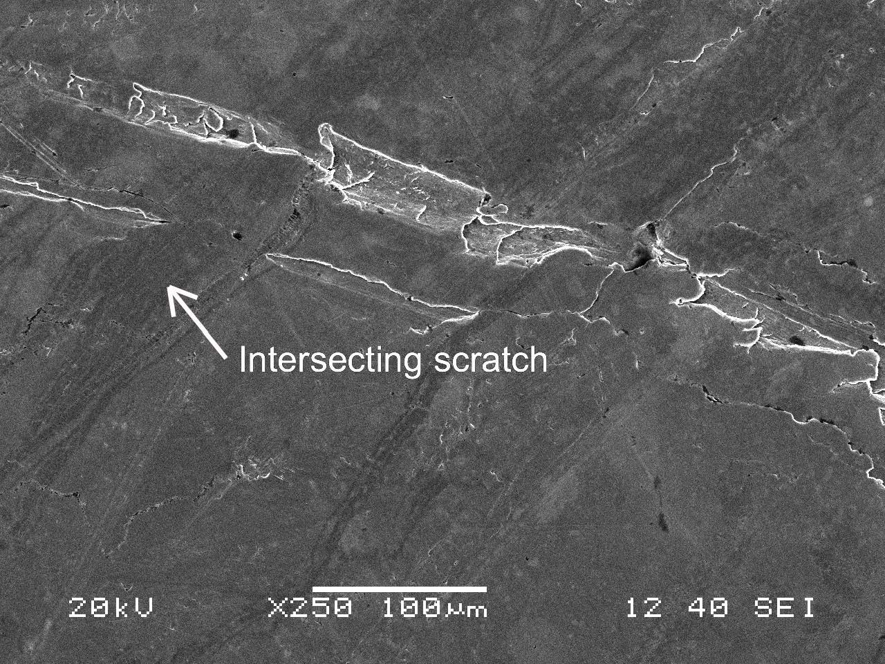
Figure 19—SEM image of roller end at higher magnification.
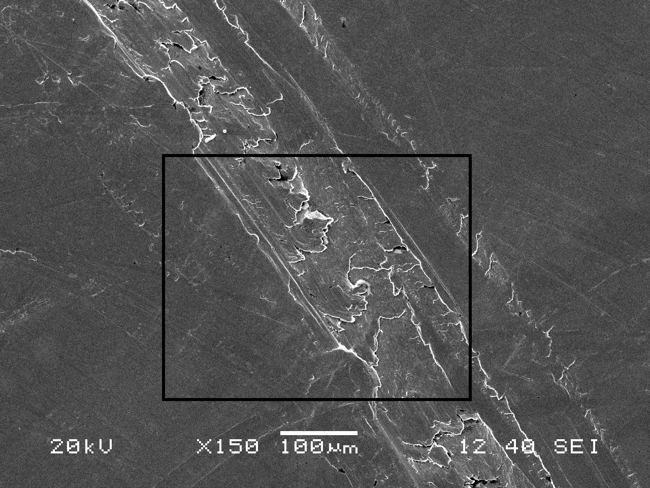
Figure 20—SEM image of the roller end at higher magnification.
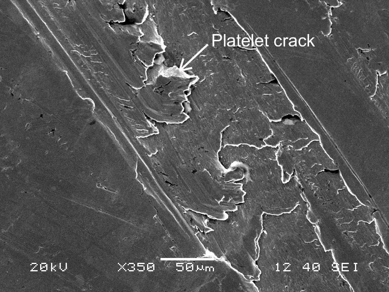
Figure 21—BSE image of the IR thrust rib.
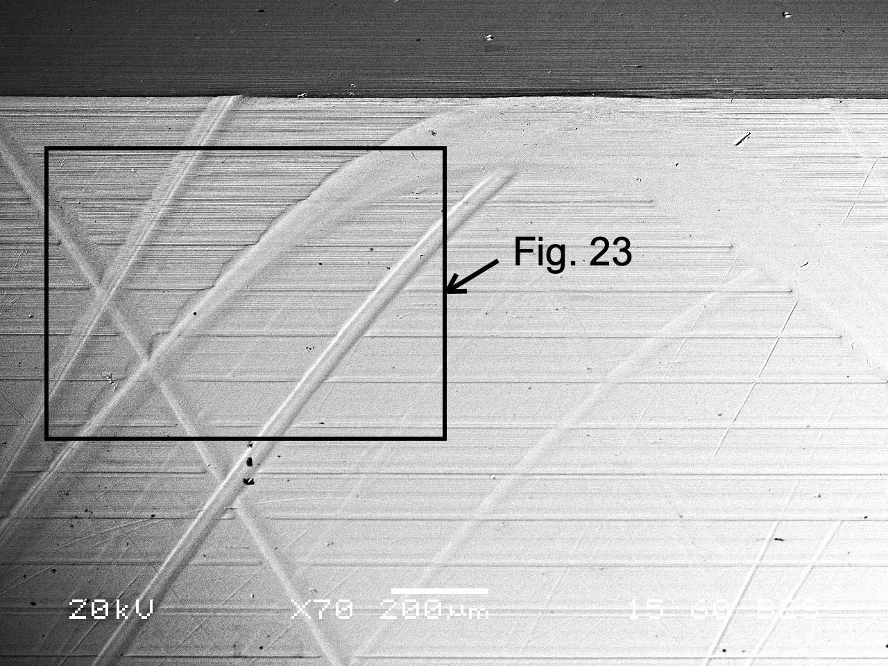
Figure 22—SEM image of the IR thrust rib.
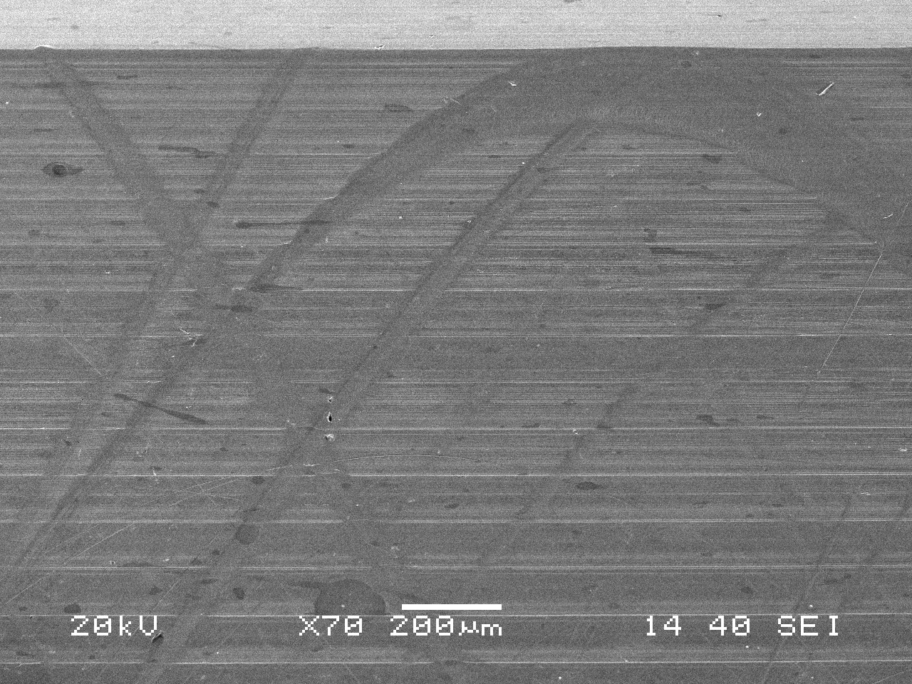
Figure 23—BSE image of the IR thrust rib at higher magnification.
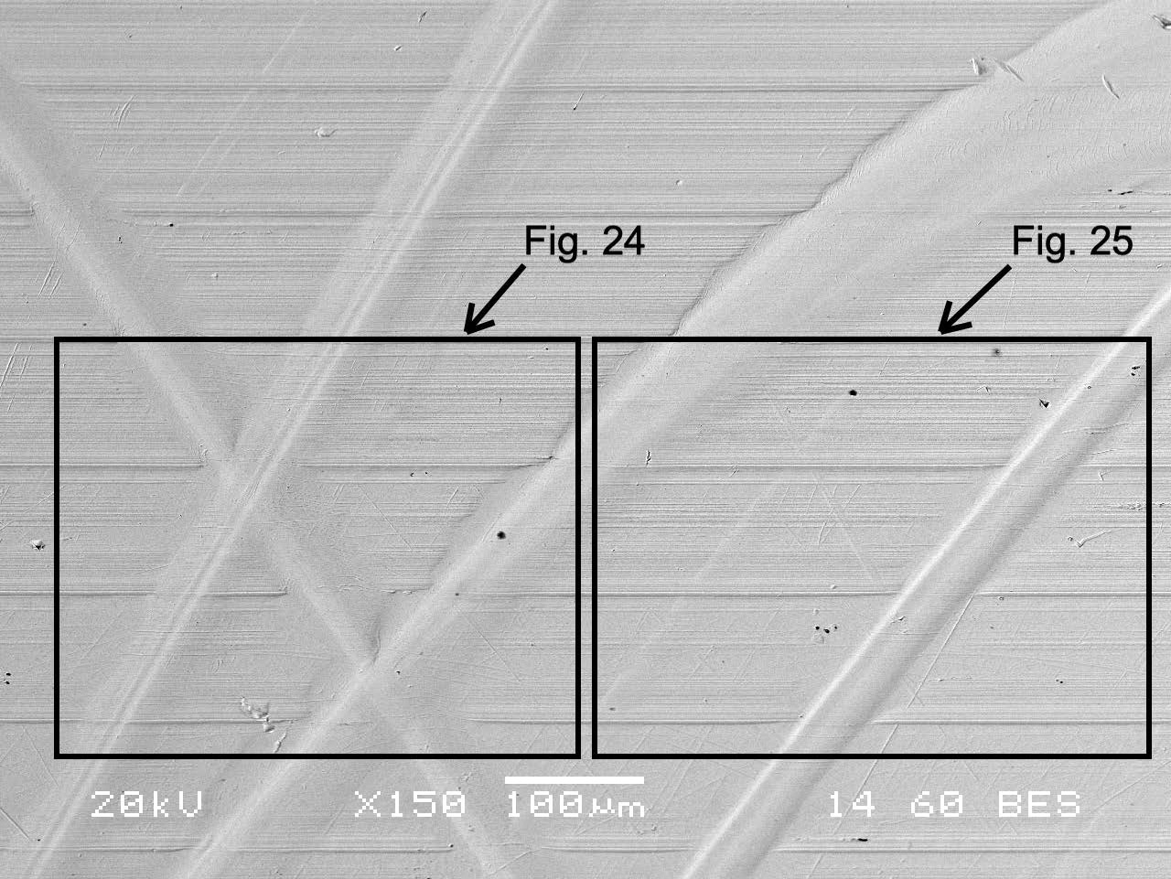
Figure 24—BSE image of the IR thrust rib at higher magnification.
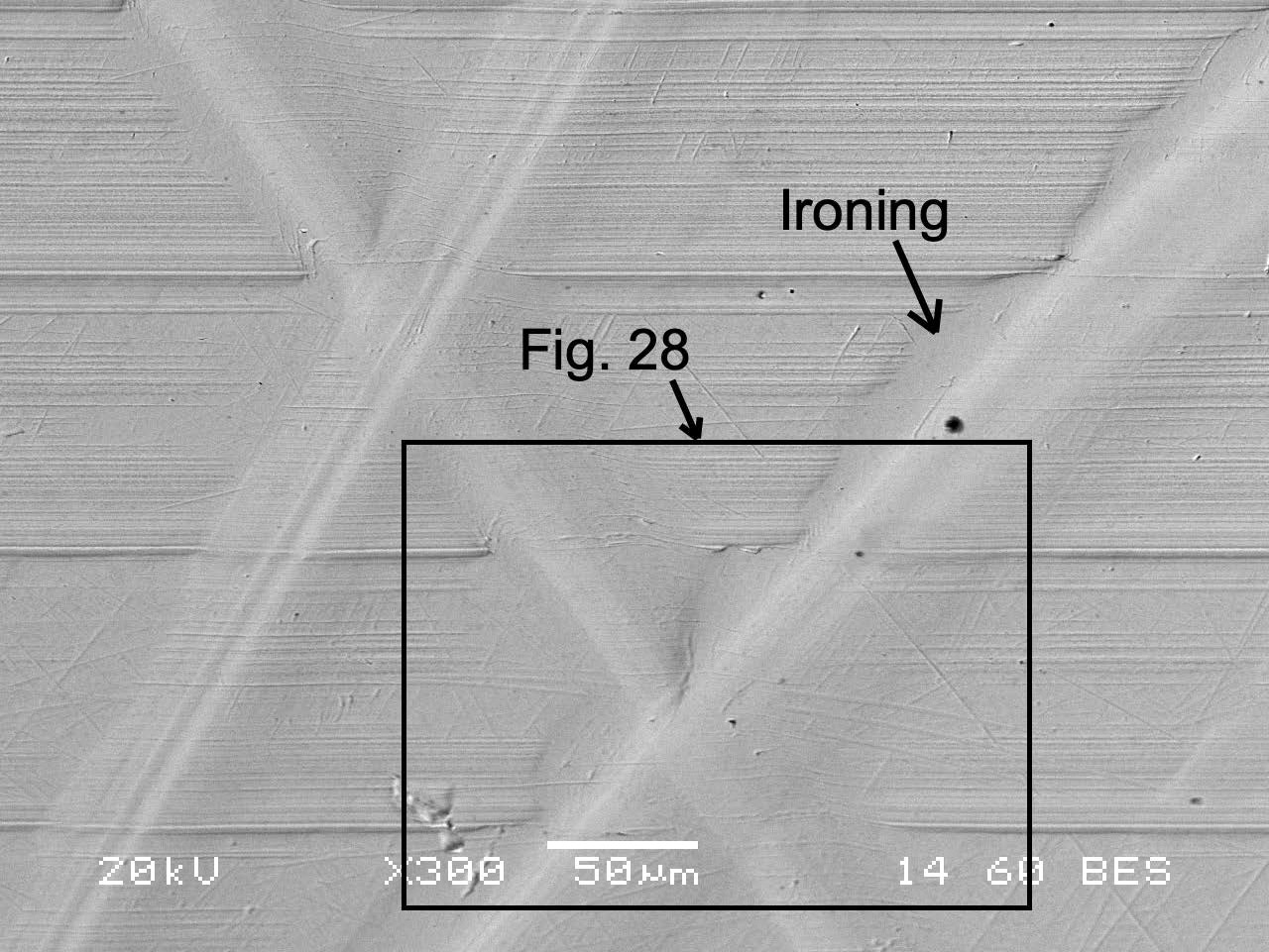
Figure 25—BSE image of the IR thrust rib at higher magnification.
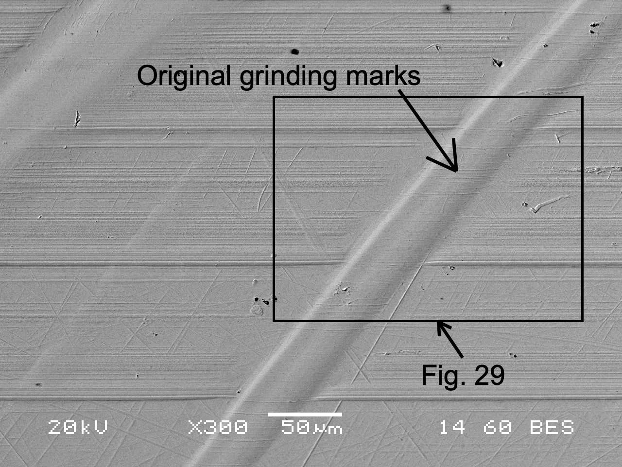
Figure 26—SEM image of Figure 25.
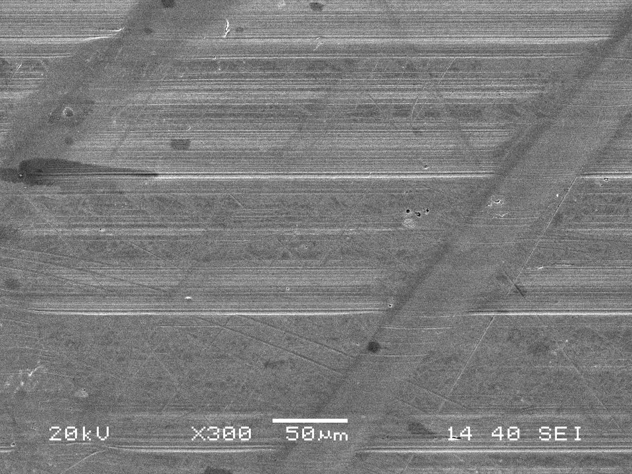
Figure 27—SEM image of Figure 24.
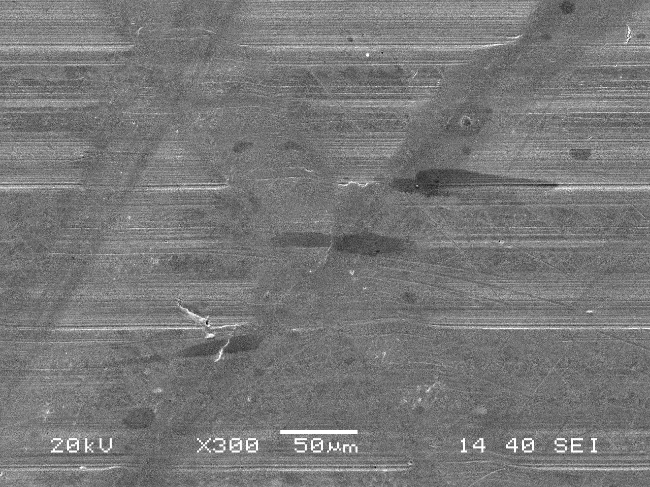
Figure 28—BSE image of the IR thrust rib at higher magnification.
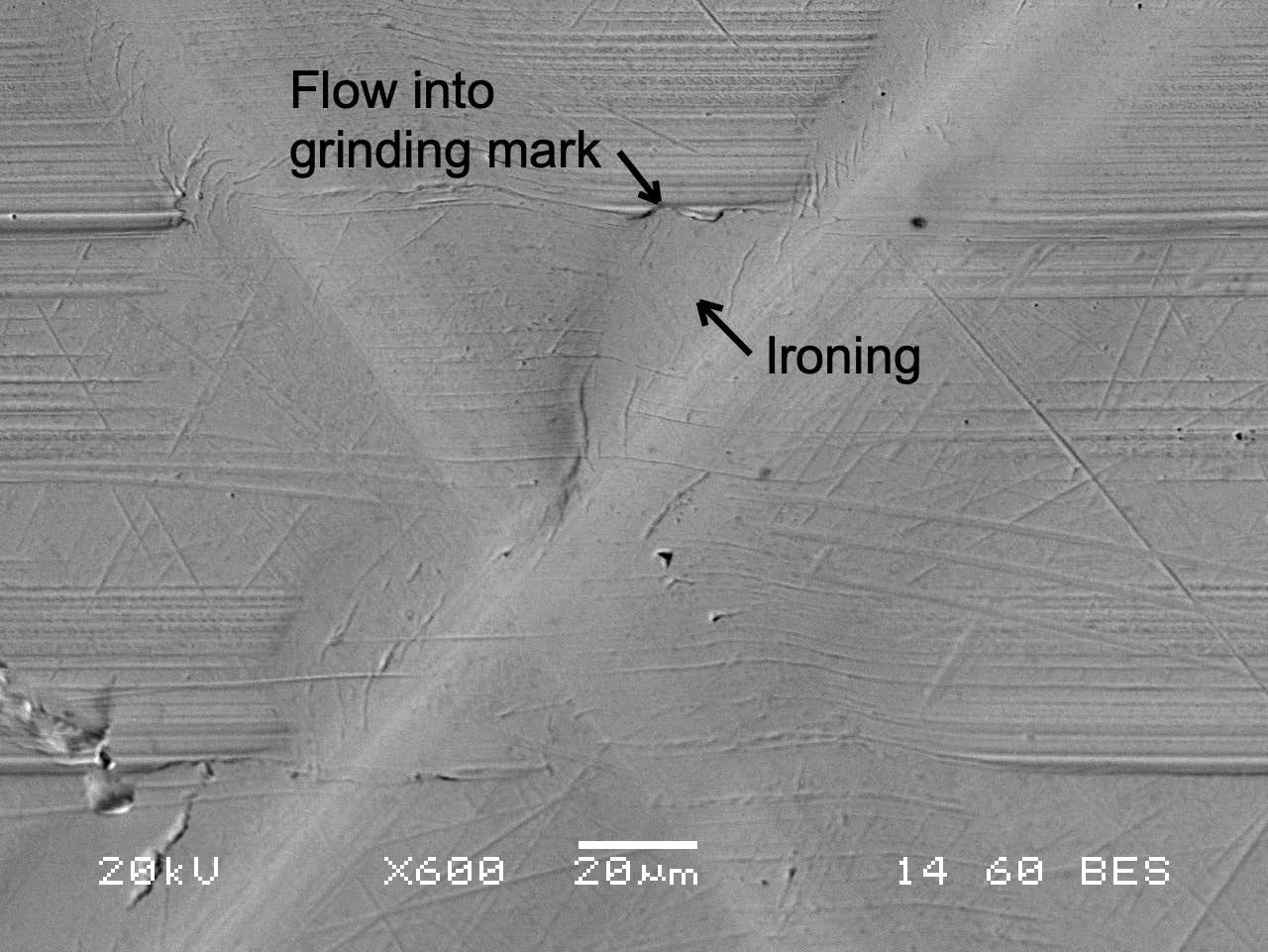
Figure 29—BSE image of the IR thrust rib at higher magnification.
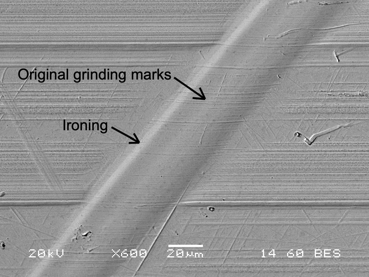
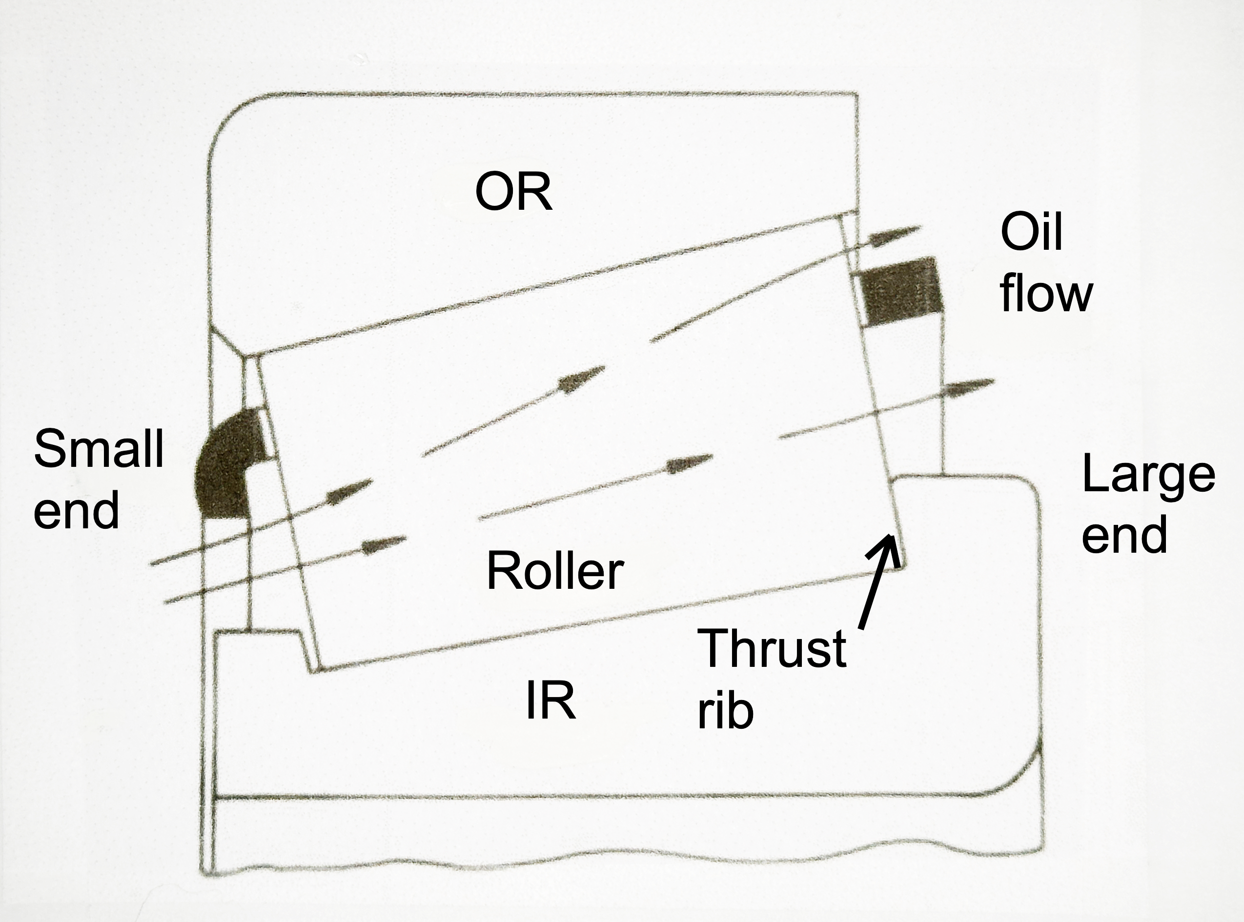
Figure 30—Lubricant flow in a TRB (Ref. 2).
